


Hall Thrusters
Ion Gridded Thrusters and Hall Thrusters are becoming the standard propulsion systems for relatively large satellites (micro and bigger) and have already made a big impact on space exploration in Smart-1 or Deep Space 1 missions, to name only a few. Currently, both technologies utilize xenon as propellant, which is chemically inert, easy to store and handle, and has low ionization cost with respect to other gases. However, for long-term missions the high cost of xenon is problematic, which prompts ESA (and others) to search for alternative propellant with better cost to efficiency ratio. Krypton (which was first suggested more than 20 years ago) shares many of the advantages with xenon, with only slightly higher ionization cost. However, despite several times lower market price, krypton has been used only experimentally because of the relatively poor efficiency of the thrusters in laboratory tests. Procurement of a krypton Hall thruster with increased efficiency would be no small achievement, which could allow the use of plasma thrusters in large interplanetary missions. In the light of current research the improvement of krypton Hall Thruster performance is possible with increased discharge voltage that also results in higher specific impulse which is a goal of its own due to propellant mass savings.
IPPLM’s Hall Thruster with nominal power of 500 W from the beginning had been designed with krypton propellant in mind and all that comes with it, for example the increased thermal loads in comparison with xenon. The reference thruster is the known and considered state-of-the-art SPT-100 with nominal power of 1350 W and discharge channel outer diameter of 100 mm.
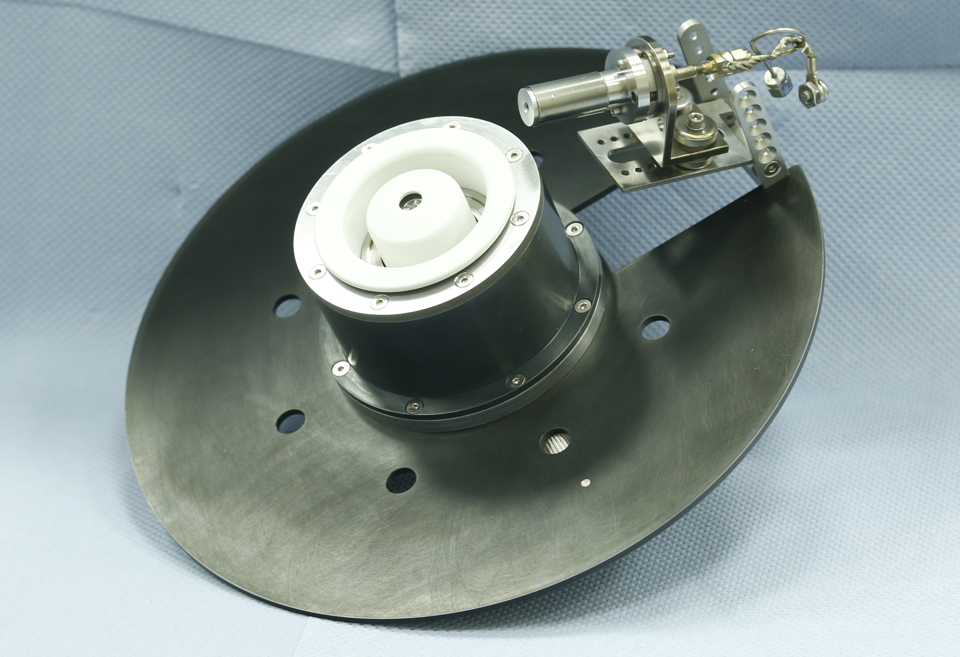
Hall Thrusters belong to the group of electrostatic thrusters operated in continuous manner, for which effective gas ionization and ion acceleration requires a static magnetic field. Neutral gas is supplied through the anode making one end of an annular ceramic channel. The other end of the discharge channel is open. The cathode is positioned outside of the channel so that an axial (mainly) electric field E is produced inside the channel. Gas density is so small that mean ionization length of the atoms is much bigger than the dimensions of the device, which prohibits effective ionization. To remedy this, a radial magnetic field B is produced near the channel exit. Electrons are “trapped” in it and drift azimuthally in the crossed fields E×B (a Hall current is induced), which allows effective ionization of the atoms by collisions with the electrons supplied by an efficient cathode (usually of the hollow type, with its own arc discharge) located outside the channel. Despite the magnetic field, the collisions allow diffusive flow of an electron current towards the anode. However, the magnetic field is weak enough not to noticeably modify the trajectories of the ions, which allows them to obtain in the electric field axial velocities 15-25 km/s. Outside the channel the ions are neutralized by the additional electrons emitted from the same cathode, and in this way travel on as a quasi-neutral plasma stream, preventing the thruster and the satellite from charging. The thruster operates for as long as it is supplied with gas and voltage. The Hall Thruster shown in the photograph is the third version developed in the scope of the KLIMT project and the starting point for the HIKHET project.
|
|
|
 |
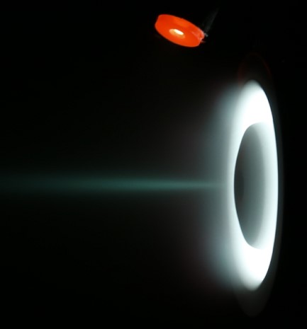 |
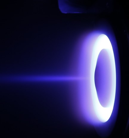
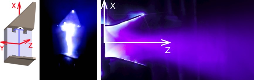
| Top: photograph of the third version of KLIMT. Attached is a commercial HeatWaveLabs cathode. Outer diameter of the discharge channel is 50 mm, channel width is 8 mm. Nominal power 500 W. Mass approximately 3 kg. Below is the thruster operating with krypton (left) and xenon (right). |
|
Pulsed Plasma Thrusters
The long-term progress of the smallest satellites assumes that they should have their own means of propulsion allowing for residual drag compensation (they are usually placed in LEO orbits), attitude changes and even orbit changes (spiral orbit rising, deorbit), so should possess functionality available in large satellites for a long time. Due to the limited mass and onboard power (several W) of a nanosatellite on one hand, and the potential total velocity change (ΔV) on the other, choosing the right propulsion type is critical. According to current knowledge, the Pulsed Plasma Thrusters are a good candidate for extending the lifetime of nanosatellites and providing maneuverability, and the thrusters themselves can be improved. It is worth noting that due to the very precise dosage of impulse bits (through repetition) the thrusters of this type can be used also in larger spacecraft when positioning accuracy is important.
Pulsed Plasma Thrusters belong to the group of electromagnetic thrusters in which the mass ablated (pre-ionized cloud of gas) from an insulator (usually Teflon) is accelerated by Ampere force f=j×B acting on current of density j flowing through the plasma produced by electrical discharge between two electrodes supplied from a battery of capacitors. The magnetic field B required to create the force stems from the same discharge current which flows in the circuit. The effectiveness of acceleration of the mass depends on physical properties of the propellant (molecular mass, ionization potential etc.) and its utilization is described by the ratio of accelerated mass to supplied mass.
Innovation of the solution proposed in the scope of the L-μPPT project consist mainly of the use of a liquid fluoropolymer as the propellant with very low vapor pressure (1e-9 mbar) and chemical composition very similar to Teflon that is typically used. Thanks to this it was possible to greatly simplify the design with respect to other devices fed with liquid propellant (water, alcohols and other volatile organic liquids have been proposed), increase the precision of the dispensing unit by using open systems (capillary pumping in open channels), better localize the ablation zone and increase the total mass of the propellant with respect to thrusters using solid polymer. It is also possible to increase the total impulse in comparison to classical systems by increasing utilization of the propellant participating in the discharge. A big advantage is also the possibility to use a common fuel tank for several thrusters when several degrees of motion need to be considered for attitude control. This aspect is mostly interesting in comparison with the systems with solid polymers, where each thruster needs its own block of fuel, which does not allow to compensate its uneven loss in case of unequal demand of the thrusters. Moreover, constant supplying of the propellant into the discharge region prevents changing of the thruster efficiency due to consumption of the Teflon block.
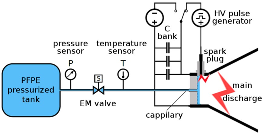
The general scheme of L-μPPT is presented in the figure below. Diverging electrodes of convergent shape are connected to a battery of capacitors and are separated by a ceramic insulator with surface of approximately 1 cm2. Open channel grooved in the insulator connects both electrodes. This channel is filled with fuel (PFPE) through a capillary which constitute the end of the supply system consisting of a tank, a micro-pump and a valve. In the figure, there are also shown temperature and pressure sensors. The voltage to which the battery is charged (750-1500 V) is insufficient to ignite the discharge on the surface of the propellant filling the channel. That is why to initiate the main discharge an additional igniter system is used, supplied from a pulsed high voltage generator (10-20 kV), like in classical Teflon thrusters. Therefore, the use of the igniter allows one to control the initiation of the discharge according to the demand, whereas the provided propellant, together with a fully charged battery, awaits in the channel without outgassing (like in thrusters with solid polymer).
 |
 |
| Scheme of L-μPPT, view of the electrodes and the channel filled with propellant and photographs of discharge on the insulator surface and the propagating plasma. |