


Vacuum facility
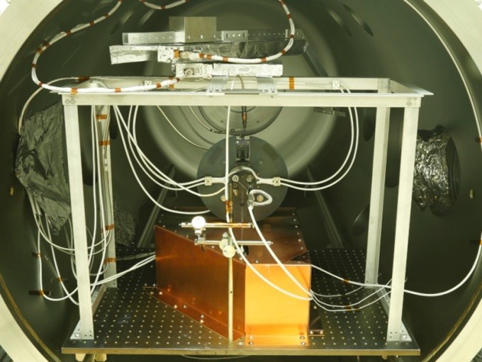
The basic piece of infrastructure is the main vacuum chamber for simulating of space environment, with volume of about 2.5 m3 and diameter of Ø1.2 m equipped with a system of oil-free vacuum pumps: Roots pump with efficiency of up to 450 m3/h, turbomolecular pump with efficiency of about 3000 l/s and a two-stage cryogenic pump with pumping speed of about 30000 l/s for nitrogen, 34000 l/s for xenon and 43000 l/s for krypton (catalog data) – see table below. This system allows to study both Pulsed Plasma Thrusters and Hall Thrusters while supplied with 3-5 mg/s of xenon, dynamically maintaining pressure in the chamber at the level of 5x10⁻⁵ mbar, which is enough to carry out relevant research.
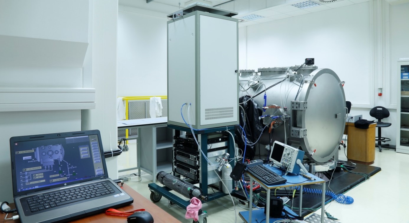 |
| Photograph of IPPLM’s vacuum facility for simulating space vacuum for experiments with PPT and HET plasma thrusters. |
Main parameters of the vacuum facility
|
Main vacuum chamber |
|||
|
Length |
2.3 m |
||
|
Diameter |
1.2 m |
||
|
Volume |
2.5 m3 |
||
|
Pump |
Rate |
Gas |
|
|
Backing pump |
Adixen ACG 600 |
450 m3/h |
Air |
|
TM pump |
Pfeiffer HiPace 3400 MC |
2.8 m3/s |
Air |
|
Cryogenic pump |
HSR Velco 900Xe |
36 m3/s |
Air (N2) |
|
34 m3/s |
Xe |
||
|
43 m3/s |
Kr |
||
Dynamic efficiency of the whole pumping system while working with krypton and xenon is, respectively, 18 m3/s and 14 m3/s, and linearity of the system is illustrated in the plot below, where the ultimate pressure is shown as a function of mass flow rate supplied into the chamber (as with working thruster). With no mass flow rate the vacuum goes down to about 3-5×10⁻⁸ mbar when all pumps are operating, and without the cryogenic pump it rises to about 2-4×10⁻⁷ mbar.
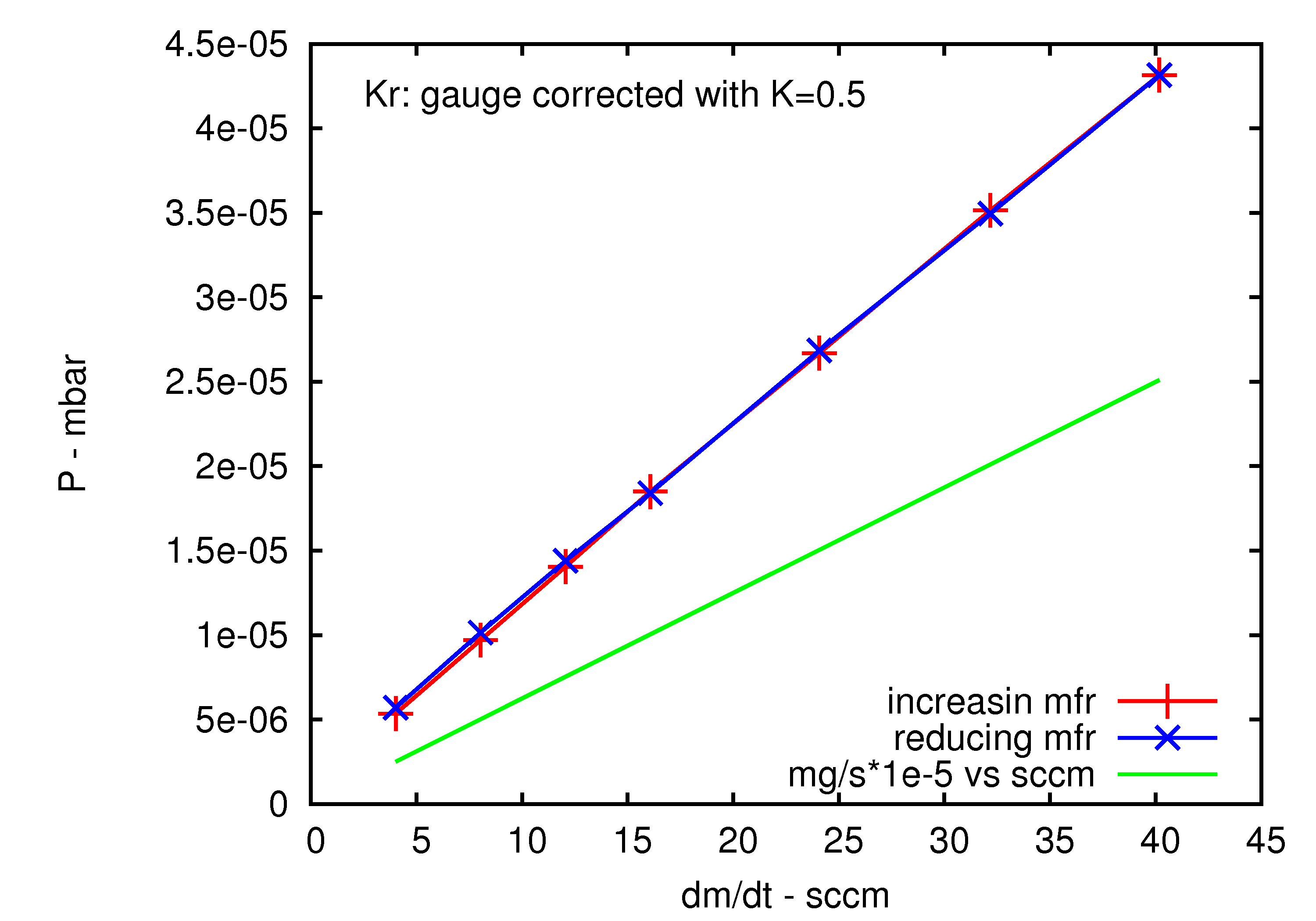 |
| Ultimate pressure in IPPLM’s chamber as a function of krypton mass flow rate supplied into the chamber (measurement with ionization gauge Oerlikon-Leybold ITR 90 Ionivac krypton-corrected) |
Besides the main vacuum chamber, the Laboratory also owns an auxiliary vacuum facility consisting of a chamber with volume of 0.035 m3 and a two-stage pumping system capable of creating vacuum at the level of 5x10⁻⁷ mbar.
 |
| Auxiliary vacuum facility. |
Gas and power supply system
For testing of Hall Thrusters a gas supply system was created relying on mass flow controllers Sierra-Instruments Smart-Trak C100L which can be used for most of inert gases. The range of chosen controllers match the needs of anode and cathode of studied Hall Thrusters (0-50 sccm and 0-6 sccm).
For supplying of the Hall Thruster with electrical power commercial power supplies are used:
Power system
|
Power unit to supply |
Voltage range [V] |
Current range [A] |
|
|
Anode |
Sorensen SGI-1000/5 |
0-800 |
0-6 |
|
Keeper |
Sorensen SGI-800/6 |
0-1000 |
0-5 |
|
Cathode heater |
Sorensen XG 40-21 |
0-21 |
0-40 |
|
Coils |
2x Sorensen XG 20-40 |
0-40 |
0-20 |
|
Filter & protecting diodes |
homemade units |
||
Diagnostics
PlaNS is equipped with a range of diagnostics allowing to comprehensively measure plasma thrusters.
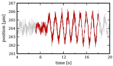
The main one is the thrust balance (produced in the scope of LμPPT project by a Swiss company MECARTEX) operating on the principle of a precise dynamometer. The device is able to measure both thrust in mN range and impulse bits in μNs range by monitoring displacement of the balance and comparing it with calibrating signal.
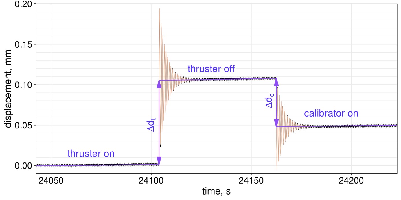 |
| Thrust measurement for Hall Thruster. |
 |
| Impulse bit measurement for PPT. |
Apart from that the Laboratory has also plasma diagnostics including Faraday probe, Langmuir probe and Retarding Potential Analyzer. They can be mounted on a special manipulator which allows to carry out measurements of the emitted plasma beam in range from -90o to +90o.
 |
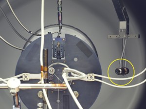 |
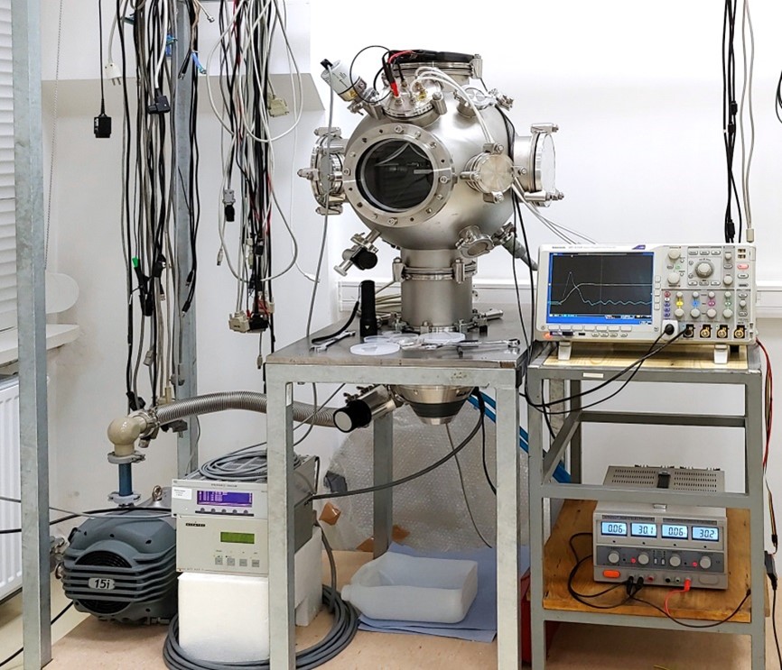
| Hall Thruster installed inside the vacuum chamber on the thrust balance. The scaffolding supporting the manipulator for the diagnostics is also visible. |
|